For companies that design, build or operate electrical infrastructure, understanding a substation’s configuration and operation is essential. Critical technical decisions depend on it: from selecting switchgear and electrical insulators, including the range of indoor and outdoor support insulators that support busbars, disconnectors and circuit breakers, to defining protection, safety and maintenance schemes that ensure service continuity and minimize unplanned outages.
This article presents the fundamental concepts of electrical substations, their types, main components and design criteria, with a perspective focused on the needs of companies, engineering firms and utilities working on HV and MV grid projects internationally.
If you need an overall view of the insulation available for these installations, we recommend reviewing our article on what types of insulators exist and what they are used for, which describes the main families later applied in substations, lines and transformer stations.
1. What is an electrical substation and what is its role in the power system?
An electrical substation is a facility intended to transform and distribute electrical energy between different voltage levels, as well as to switch, protect and measure the lines and equipment connected to it. It works as an interchange point between generation, transmission and distribution, and its design is tailored both to grid requirements and to the environmental and regulatory conditions of each country or region.
In this context, it is key to keep in mind the criteria set out in “what regulations govern the manufacturing and use of electrical insulators“, since they directly influence the choice of insulation components for the substation.
In practical terms, the substation acts as a “nerve center” from which energy flow is controlled: lines are connected or disconnected, loads are rerouted, the appropriate voltage level is ensured, and the system is protected against electrical faults and abnormal operating conditions. To understand the impact of an insulation failure in this context, we recommend reading “what types of failures can occur in insulators and how they affect safety“.
1.1. The substation’s position in the generation–transmission–distribution chain
To understand the role of the substation, it helps to place it within the classic chain of the electrical system:
- Generation: electrical energy is produced at power plants (thermal, hydroelectric, wind, photovoltaic, nuclear, etc.). Generation voltage is usually relatively low compared to transmission levels.
- Transmission: high and extra-high voltage lines carry energy over long distances, reducing losses. Here, step-up and step-down substations appear alongside major transmission corridors.
- Distribution: from the transmission grid, energy “branches out” through medium- and low-voltage networks that bring supply closer to industrial parks, critical infrastructure and end users.
Electrical substations can be present at different points in this chain:
| System stage | Typical substation type | Main function |
|---|---|---|
| Generation | Step-up substation | Steps up generation voltage to levels suitable for long-distance transmission. |
| Transmission | Interconnection, through or distribution substations | Connect high-voltage lines, enable switching and sectionalizing of sections and redistribute power. |
| Distribution | Step-down substation | Reduces transmission voltage to medium or low voltage levels to supply distribution networks and large consumers. |
Depending on the phase of the system in which they are located, substations handle different voltage and current levels, which directly determines the selection of switchgear, insulators, surge arresters and fittings suitable for each project.
If you want to see how this translates into specific components, in our post “what types of insulators are commonly used in substations” we analyze the most common solutions for this type of installation.
1.2. Main functions: voltage transformation, switching, protection and measurement
Although a substation’s architecture may vary, virtually all of them share a set of basic functions:
- Voltage transformation: using power transformers, the incoming voltage level is adapted to the level required at the output (for example, from 220 kV to 66 kV, or from 132 kV to 20 kV). This function is essential to optimize the balance between technical losses, infrastructure cost and safety requirements, and is closely linked to the criteria detailed in “how to choose the right insulator for a high-power transformer“.
- Switching and sectionalizing: the substation allows circuits to be opened and closed, lines, transformers and other equipment to be connected or disconnected using circuit breakers, disconnectors and reclosers. This makes maintenance work easier, supports contingency management and enables flexible grid operation. For these switching operations to be carried out safely, it is important to follow the recommendations shared in “how to ensure proper installation of insulators to maximize their performance“.
- Protection: through protection relays, instrument transformers, power circuit breakers and tripping systems, faults (short circuits, overloads, ground faults, etc.) are detected and isolated quickly and selectively. Coordination between these elements is critical to limit damage and maintain system stability.
- Measurement and supervision: systems are installed to measure voltage, current, power, energy, power quality and other parameters, both for billing and for real-time operation and post-analysis of the grid. It is increasingly common to complement them with advanced solutions such as those described in “what technologies enable real-time monitoring of the condition of insulators“.
A well-designed substation does not only fulfill transformation functions. It makes it possible to operate the grid flexibly, limit the impact of faults and ensure that energy reaches the consumer with the required quality level.
To guarantee these functions, insulated components (busbars, connections, measuring and switching equipment) rely on a range of electrical insulators and fittings that must be correctly dimensioned for voltage, pollution, mechanical stress and local environmental conditions. In especially harsh environments, solutions such as POINSA’s range of polymeric insulators can improve outdoor performance, provided they are combined with maintenance practices such as those described in “what preventive maintenance is needed to extend the lifespan of insulators“.
1.3. Differences between a substation, a transformer station and other facilities
In everyday language within the power sector, it is common to use terms such as substation, transformer station or sectionalizing station in a seemingly similar way. However, there are relevant differences, especially from a design standpoint, in terms of voltage levels and installation complexity.
- Electrical substation: usually associated with high and extra-high voltage installations (although it may also include medium-voltage levels) where transformation, switching and protection functions are performed between different networks or grid sections. Its footprint, number of bays and switchgear complexity are typically high, and in many cases “ceramic insulators” are used, specifically designed to provide the creepage distances and mechanical strength required by these voltage levels.
- Transformer station (TS): in many countries this refers to installations closer to the consumer, generally medium to low voltage (for example, from 20 kV to 400/230 V) supplying urban areas, buildings or industries. Their size is smaller and they are often compact solutions (prefabricated kiosk, building, underground, etc.), so it is particularly useful to apply the criteria explained in “how to choose an insulator for indoor and outdoor electrical networks“.
- Sectionalizing or switching stations: installations whose main purpose is to connect, disconnect or reconfigure lines, without necessarily transforming the voltage level. They are used to improve operational flexibility and selectivity in the network.
This differentiation has clear implications for the specification of equipment and components:
- In high-voltage substations, insulation requirements, creepage distances and mechanical capacity of insulators and fittings are especially demanding.
- In transformer stations, compact and modular solutions are prioritized, with enclosed switchgear and reduced maintenance requirements.
In many projects, achieving this balance involves incorporating “custom insulators and made-to-measure products” that adapt to each installation’s constraints without compromising electrical safety.
Once the role of the substation within the power system and the difference compared to other installations are understood, the next step is to analyze the types of electrical substations, their classification and the contexts in which each one is used.
If you are interested in how these configurations are adapting to new grids, we recommend reading “what innovations are impacting the distribution of electric power“.
2. Types of electrical substations
Electrical substations can be classified in different ways depending on the criterion used as a reference: voltage level, system function, network configuration or even construction solution. Understanding this classification helps engineering firms, utilities and industrial companies better define technical specifications and component selection, including electrical insulators and associated fittings—especially relevant when looking for solutions such as those analyzed in “which insulators offer greater resistance to mechanical and electrical impacts” or in “what international regulations ensure insulator quality“.
2.1. Classification by voltage level (HV, MV, LV)
One of the most common criteria for classifying substations is the voltage level at which their main busbars and associated lines operate. Although the specific ranges may vary by country and regulation, generally speaking one can refer to:
| Voltage level | Typical range (kV) | Most common use |
|---|---|---|
| Extra-high voltage (EHV) | ≥ 220 kV | Long-distance transmission corridors and interconnections between large load areas. |
| High voltage (HV) | Between ~66 kV and 220 kV | Transmission and main distribution networks, supply to large urban and industrial substations. |
| Medium voltage (MV) | Between ~1 kV and 36 kV | Distribution networks and supply to transformer stations and large consumers. |
| Low voltage (LV) | ≤ 1 kV | Final supply to residential, commercial and light industrial users. |
Depending on this range, the substation will require insulators, switching equipment and structures with very different mechanical and electrical characteristics. In installations located in especially aggressive environments, these requirements become even more demanding and it is advisable to consider criteria such as those described in “how extreme weather conditions affect insulator customization“. For example:
- In EHV and HV, insulators must provide high creepage distances, withstand high mechanical stresses (due to conductor weight and wind) and adapt to often aggressive environments (industrial pollution, coastal environments, etc.).
- In MV, in addition to line and support insulators, compact solutions, switchgear cells and enclosed equipment are highly relevant, where insulation design may be in air, resin or gas.
2.2. Line infeed/outfeed, through and distribution substations
Another common criterion is based on the substation’s function within one or more transmission or distribution lines. From this perspective, the following can be distinguished, among others:
Line infeed/outfeed substations
These are substations where a high-voltage line enters the substation and exits again toward another section of the network, establishing a connection point to a consumption area or to another transmission network. They are used to supply new areas, large consumers or to interconnect systems.
- They include incoming and outgoing line bays, usually symmetrical.
- Their design must facilitate sectionalizing and branching operations, ensuring selectivity in case of fault.
- Support and suspension insulators play a key role in the mechanical reliability of incoming and outgoing strings.
Through substations
In this type of installation, the line passes through the substation and mainly switching and sectionalizing functions are performed, without necessarily transforming the voltage level. They are used to increase the operational flexibility of long transmission corridors.
In these substations, the following become particularly important:
- Busbar configuration and couplings between lines.
- Coordination between circuit breakers, disconnectors and protections.
- Dimensioning of support insulators and bushings to ensure insulation continuity between bays.
Distribution substations
Their main objective is to redistribute energy toward multiple outgoing lines feeding different areas or voltage levels. They are very common in urban and industrial environments, where a substation receives energy from the transmission grid and distributes it to several distribution networks.
From a hardware standpoint:
- The number of outgoing bays increases, implying a higher number of busbar sets, disconnectors and insulators.
- Space optimization and support structures are key, especially in environments with footprint limitations.
2.3. Step-up, step-down and intermediate substations
If we primarily consider the voltage transformation function, three major types of substations can be distinguished:
Step-up substations
These are usually located at the output of generation plants or large renewable parks (wind, photovoltaic, etc.). Their mission is to raise the voltage from medium levels to high or extra-high levels, enabling long-distance transmission with lower losses.
- They often operate between MV/HV or HV/EHV.
- They require high-capacity power transformers and insulators with high mechanical and electrical strength, especially on overhead line exits.
- They are critical for integrating renewable sources into the transmission grid.
Step-down substations
These substations reduce voltage from the transmission grid to levels suitable for distribution or for direct consumption by large industrial facilities. In traction applications, these step-down substations are combined with specific equipment to supply catenaries and railway traction systems, where solutions such as POINSA’s railway insulators help align electrical, mechanical and environmental requirements within a single design.
Typical examples include:
- Reduction from 220 kV to 66 kV or 45 kV for high-voltage distribution networks.
- Reduction from 132 kV to 20 kV for medium-voltage distribution networks.
- Reduction from HV/MV for large industrial plants with their own substation.
They combine:
- Switchgear and insulators suitable for the high-voltage incoming side.
- More compact and modular solutions for the medium-voltage side, often in buildings or indoor switchgear cells.
Intermediate or interconnection substations
These connect networks of similar or slightly different voltage and perform both transformation and switching/distribution functions. For example, links between 132 kV and 110 kV networks, or between different areas of the same transmission grid.
Their complexity can be high because:
- They must ensure link reliability between systems that, in many cases, act as mutual backup.
- They may include multiple busbar schemes, sectionalized couplings and high equipment redundancy.
Once the main types of electrical substations have been reviewed, the next step is to analyze in detail the elements that compose them: transformers, switching equipment, busbars, electrical insulators, surge arresters, structures and many other components that determine the overall reliability of the installation.
3. Main elements of an electrical substation
An electrical substation is made up of a set of equipment and structures that work in a coordinated way to ensure the transformation, switching, protection and measurement of electrical energy. Beyond the large visible equipment (such as power transformers), there are many “silent critical components”: insulators, fittings, support structures and accessories that determine the overall reliability of the installation.
The following describes the main elements typically found in a high- and medium-voltage substation, highlighting, where relevant, the role played by electrical insulators and associated components.
3.1. Power and instrument transformers
Power transformers are the heart of the substation when it comes to changing the voltage level between the incoming and outgoing networks. They are designed to operate continuously, withstanding high current and voltage levels, and managing significant apparent power.
- Power transformers: perform conversion between two or more voltage levels (for example, 220/66 kV or 132/20 kV). They consist of a magnetic core, windings, insulation system, tank, oil conservator and a wide range of accessories (tap changer, Buchholz relays, valves, etc.).
- Instrument transformers: include current transformers (CTs) and voltage transformers (VTs or PTs), used to feed protection, measurement and control systems with standardized current and voltage levels.
Around these units, bushings and specific insulators are installed to allow a safe transition between the internal parts of the transformer and the external switchgear. The quality of the external insulation, as well as the fastening fittings, is essential to prevent surface discharges, leaks and unwanted mechanical stresses on the connections. ; in “what maintenance transformer bushings require” it is detailed how to keep these elements in optimal condition throughout the transformer’s service life.
3.2. Switching equipment: circuit breakers, disconnectors, reclosers
Switching equipment makes it possible to connect and disconnect lines, transformers and other equipment under different load and fault conditions. Its main elements are circuit breakers, disconnectors and reclosers, which must meet the dielectric and mechanical requirements set out in standards. Its main elements are:
- Power circuit breakers: designed to open and close the circuit under load and even interrupt short-circuit currents. They may be oil, compressed air, SF6 or newer technologies with alternative gases and hybrid solutions.
- Disconnectors: allow circuits to be opened and closed under no-load conditions, ensuring a visible isolation gap. They are used to physically isolate equipment and lines during maintenance and to establish safe operating configurations.
- Reclosers and automatic disconnect switches: common in medium-voltage networks, they allow automatic reclosing after a transient fault and improve service continuity indices.
All these devices are supported by support insulators that raise conductors and moving contacts to the required height, maintaining insulation distance to ground and between phases. The mechanical strength of these insulators is critical to withstand:
- Dynamic stresses during opening and closing operations.
- Forces due to short circuits.
- Loads from wind, ice or vibrations transmitted through the structures.
3.3. Busbars and connection lines
Busbars are the elements that interconnect different bays of the substation (lines, transformers, auxiliary services, etc.) according to the defined single-line diagram (single bus, double bus, ring, breaker-and-a-half, etc.).
Busbars may consist of:
- Rigid aluminum conductors or alloys, mounted on metal structures.
- Flexible conductors in certain configurations, especially on exits to overhead lines.
These busbars and connections are fixed to structures using:
- Support insulators that provide the required level of insulation to ground.
- Fittings and joining accessories (clamps, connectors, terminals, dead-ends) that ensure electrical continuity and mechanical strength of the connections.
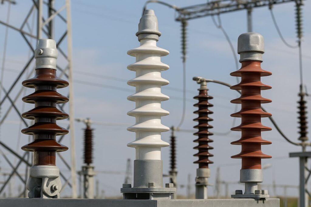
3.4. Electrical insulators: types, functions and location in the substation
Electrical insulators are essential components in any substation because they allow:
- Mechanical support of conductors, busbars and equipment.
- Electrical insulation to ground and between phases.
- Resistance to demanding environmental conditions (pollution, humidity, UV radiation, etc.).
In a typical substation you can find different types of insulators:
- Support insulators: support rigid busbars, disconnectors and circuit breakers. They must combine high mechanical strength with high dielectric performance.
- Suspension and strain insulators: more common in incoming and outgoing overhead line strings, where they support conductor weight and wind/ice loads.
- Wall bushings or bushings: allow conductors to pass through walls, roofs and metal enclosures, ensuring insulation between inside and outside.
Depending on the technology and environment, insulators may be:
- Ceramic (porcelain): widely used in high voltage, with good mechanical and thermal resistance.
- Toughened glass: common in suspension and strain strings of overhead lines.
- Polymeric (silicone, composite): especially interesting in polluted environments and coastal areas, due to their contamination performance and lower weight.
Correct coordination between insulators, fittings and structures is a key factor in ensuring substation availability and reducing insulation-related failures. When deciding between porcelain and polymers, it is useful to review the technical comparisons in “how to compare the durability of ceramic and polymer insulators” and, from an environmental perspective, the criteria set out in “how ceramic insulators contribute to sustainability“.
3.5. Surge arresters, earthing switches and protection systems
Substations must be protected against overvoltages, both of atmospheric origin (lightning) and from switching operations. For this, the following are used:
- Metal-oxide surge arresters: connected between phase and ground, they limit overvoltages to values the substation equipment can withstand, discharging energy to the grounding system.
- Earthing switches: allow intentional grounding of certain parts of the installation (for example, an out-of-service line) to ensure safety during work.
- Protection systems: based on protection relays, instrument transformers, power circuit breakers and communication systems, which act in a coordinated way under fault conditions.
The effectiveness of these systems is closely linked to good ground grid design and to correct insulation coordination for the rest of the components (insulators, creepage distances, withstand levels against lightning and switching impulses).
Top priority objective: ensure that, in the event of an overvoltage, the current path is controlled and safe, protecting high-value equipment and avoiding risks to personnel.
3.6. Support structures, fittings and associated mechanical components
Finally, but no less important, metal structures, fittings and other mechanical components form the substation’s skeleton:
- Metal poles and gantries: support the insulator strings of incoming and outgoing lines, as well as some outdoor switchgear. They must be designed to withstand wind, ice, seismic loads and stresses derived from short circuits.
- Equipment supports: foundations for transformers, structures for circuit breakers, disconnectors and surge arresters, among others.
- Line fittings and accessories: clamps, connectors, links, bolts, tensioners and a wide set of elements that allow the mechanical fixation of conductors, insulators and equipment to structures.
These elements must be manufactured with suitable materials (galvanized steel, aluminum alloys, etc.) and designed to withstand mechanical and environmental loads throughout the substation’s service life. In addition, it is essential to:
- Ensure good corrosion resistance, especially in industrial or marine environments.
- Avoid stress concentrations that can cause premature fatigue.
- Ensure proper compatibility between fittings, insulators and conductors.
In the following sections, we will address the design criteria that determine the selection of these components, as well as the international standards that apply to substations and electrical insulators in high- and medium-voltage projects.
4. Electrical substation design: basic technical criteria
Designing an electrical substation is not limited to placing equipment on a plot of land. It requires integrating electrical, mechanical, safety, environmental and regulatory criteria into a coherent and optimized scheme. Correct design facilitates operation, reduces maintenance costs and improves long-term reliability.
This block addresses some of the basic technical criteria that determine substation configuration and the selection of its key components, with special attention to electrical insulators and associated elements.
4.1. Insulation levels and insulation coordination
One of the fundamental design aspects is insulation coordination, i.e., defining the insulation levels necessary so that equipment and the installation can withstand expected overvoltages (atmospheric and switching) without causing unwanted disruptive discharges.
To do this, the following are considered:
- Nominal and maximum service voltage levels.
- Temporary overvoltages, switching overvoltages and lightning impulses.
- Characteristics of the grounding system and surge arresters.
- Geometry of equipment, conductors and structures.
In practice, parameters such as the following are defined:
- Lightning impulse withstand voltage (LIWL).
- Switching impulse withstand voltage (SIWL).
- Power-frequency withstand voltage in dry and wet conditions.
These values are used to specify the insulation of:
- Support, suspension and bushing insulators.
- Air clearances between phases and to ground.
- Coordination with surge arresters and overvoltage protection systems.
| Parameter | Purpose | Design impact |
|---|---|---|
| LIWL | Withstand lightning-origin impulses. | Defines air clearances and insulator characteristics. |
| SIWL | Withstand switching overvoltages in HV/EHV. | Affects the dimensioning of high-voltage switchgear. |
| Wet withstand voltage | Assess behavior under rain, fog, etc. | Influences insulator profile and creepage length. |
Key idea: oversized insulation increases cost; insufficient insulation increases the risk of discharges and failures. Optimal design is based on precise coordination between equipment, insulators and surge arresters.
4.2. Safety clearances and creepage distances on insulators
Safety clearances and creepage distances are decisive parameters in the physical design of the substation. They determine phase-to-phase spacing, structure size and the type of insulators to be used.
- Air clearance: minimum space between live parts and ground, or between phases, to avoid disruptive discharges.
- Creepage distance: length measured along the insulator surface between the live part and the grounded part. It is especially relevant in polluted environments.
To define these distances, factors are taken into account such as:
- Voltage level and overvoltage category.
- Pollution category (light, medium, severe, very severe).
- Altitude above sea level.
- Weather conditions (humidity, salt fog, industrial dust, etc.).
Incorrect selection of creepage distances can cause:
- Repeated surface discharges, which degrade the insulator.
- Loss of insulation under fog, rain or dirt conditions.
- Increased risk of dielectric failures and protection trips.
That is why manufacturers of substation components design specific insulator ranges adapted to different pollution conditions and voltage levels, enabling engineering firms and utilities to select the most suitable solution for each project.
4.3. Environmental conditions: pollution, altitude, climate
The environment in which a substation is installed has a direct impact on its design. Designing a facility in:
- An industrial area with a polluted atmosphere
- A coastal region with salt fog
- A desert area with dust and sand
- A high-mountain region with low atmospheric pressure and extreme cold conditions
is not the same.
Among the main environmental effects to consider are:
- Pollution: increases the conductivity of insulating surfaces, raising the risk of surface discharges. It is compensated with greater creepage distances, selection of appropriate materials (for example, polymeric insulators) and, in some cases, washing plans.
- Altitude: at higher altitude, air density is lower, reducing dielectric strength. This forces an increase in air clearances and a review of equipment performance.
- Temperature and UV radiation: influence the aging of polymeric materials and the thermal expansion of metal elements.
- Wind, snow and ice: affect the mechanical dimensioning of structures, insulators and fittings due to additional loads they must withstand.
| Environmental condition | Main risk | Typical measures |
|---|---|---|
| Coastal area | Salt pollution, corrosion. | Insulators with greater creepage, anti-corrosion materials, periodic washing. |
| Industrial area | Deposits of dust and conductive fumes. | Specific insulator profiles, scheduled cleaning, greater creepage distance. |
| High mountains | Lower dielectric strength of air, ice and snow. | Increased air clearances, reinforced structures, specific load calculations. |
4.4. Busbar configurations and typical single-line schemes
A substation’s single-line diagram defines how lines, transformers, busbars and auxiliary services are interconnected. This configuration has a direct impact on the installation’s reliability, operational flexibility and cost.
Among the most common schemes are:
- Single bus.
- Double bus.
- Breaker-and-a-half.
- Ring bus.
- Hybrid schemes and compact GIS configurations.
As a conceptual summary:
| Scheme | Advantages | Disadvantages |
|---|---|---|
| Single bus | Simple and economical, easy to operate. | Less redundancy; a bus fault affects all bays. |
| Double bus | Greater operational flexibility; ability to transfer bays from one bus to another. | More expensive; greater design and operating complexity. |
| Breaker-and-a-half | High reliability and flexibility; maintains service under many contingencies. | Complex scheme; requires more circuit breakers and more detailed engineering. |
These configurations determine:
- The number and arrangement of support insulators for busbars and equipment.
- The geometry of metal structures supporting the switchgear.
- The length and arrangement of conductors and joining fittings.
Once the basic design criteria are established, the next step is to review the standards and international regulations that apply to electrical substations and the components they incorporate, including insulators, fittings and structures for high and medium voltage.
5. Standards and regulations applicable to electrical substations
In electrical substation projects with an international scope, the applicable standards are central from basic engineering through manufacturing, assembly and commissioning. The requirements for design, testing and certification of equipment—including electrical insulators, fittings and structures—are defined by a set of standards that ensure safety, interoperability and installation quality. This regulatory foundation is directly connected to the certification requirements analyzed in the article what certifications insulators need to enter international markets.
Although each country may have its own specific regulations, there is a core set of international standards (IEC, IEEE, EN, etc.) widely accepted by utilities, engineering firms and manufacturers in high- and medium-voltage projects.
5.1. Main related IEC and IEEE standards
The IEC (International Electrotechnical Commission) and the IEEE (Institute of Electrical and Electronics Engineers) are the two reference organizations for electrical standardization worldwide. Their standards cover everything from the definition of voltage levels to test methods for insulators, transformers, switchgear and protection systems.
As a guideline, substation projects typically consider:
- IEC standards for high-voltage equipment: define requirements for switchgear, insulators, surge arresters, instrument transformers, etc.
- IEC standards for insulation coordination and dielectric tests: specify withstand voltage levels, test waveforms and acceptance criteria.
- IEEE/ANSI standards: widely used in North American projects and in countries adopting this framework, with criteria that are equivalent but not always identical to IEC.
In practice, many internationally active companies work with product catalogs capable of meeting, project by project, IEC or IEEE requirements, thus ensuring adaptability to different markets. When the project involves exporting to the European Union, what is explained in “how European regulations affect export electrical insulators” is particularly relevant.
| Scope | Main objective | Impact on the project |
|---|---|---|
| IEC high voltage | Define design and test requirements for HV/EHV equipment. | Basis for technical specification of switchgear and insulators. |
| IEC/IEEE insulation coordination | Establish withstand voltage levels and impulse tests. | Defines air clearances, creepage levels and surge arrester characteristics. |
| IEEE/ANSI for substations | Specify design criteria, equipment and testing in ANSI environments. | Reference for projects in North America and countries with ANSI standards. |
5.2. Quality requirements and tests for insulators and switchgear
Within the substation, electrical insulators, switching equipment and surge arresters must pass a series of type and routine tests to verify that they meet the required electrical and mechanical stress levels.
Common tests include:
- Dielectric tests: power-frequency, lightning impulse and switching impulse.
- Mechanical tests: tensile, bending, compression and torsion stresses on insulators and fittings.
- Thermal and heating tests: to verify the behavior of conductors, busbars and contacts.
- Aging and pollution tests: especially relevant for polymeric and ceramic insulators.
These tests are carried out according to specific standards, which define:
- The test methodology (setup, applied voltages/loads, number of cycles, etc.).
- The acceptance criteria (absence of punctures, permanent deformations, insulation loss, etc.).
- Requirements for marking and traceability of tested products.
Specialized manufacturers of substation components typically offer:
- Insulator and fitting ranges with standardized designs tested to IEC/IEEE.
- Possibility of additional or project-specific tests at the request of the customer or utility.
- Technical documentation and certificates that facilitate approval in different markets.
5.3. Certifications and common criteria in international projects
In addition to strict compliance with technical standards, international substation projects often require a set of certifications and best practices related to quality management, environment, safety and social responsibility.
Among the most common are:
- ISO 9001: quality management systems.
- ISO 14001: environmental management.
- ISO 45001 (or OHSAS 18001): occupational health and safety.
- Specific requirements for material traceability, dimensional control, galvanizing or coating processes, etc., in the case of structures and fittings.
From a contracting standpoint, utilities and large international clients often include:
- Approved manufacturer lists for insulators, fittings, surge arresters and switchgear.
- Prior experience requirements in similar projects (references from installations in service).
- Technical audits of factories and production processes.
For companies delivering substation projects internationally, collaborating with manufacturers that already comply with IEC/IEEE standards and hold ISO certifications reduces approval lead times, simplifies purchasing, and lowers the project’s technical and documentation risk.
With this regulatory framework in mind, the next step is to review the most common construction typologies of substations—outdoor, indoor and GIS—and how they affect the selection of equipment, insulators and fittings.
6. Construction typologies: outdoor, indoor and GIS substations
In addition to their function and voltage level, electrical substations differ by their construction typology. The choice between an outdoor air-insulated (AIS) solution, an indoor substation or a gas-insulated substation (GIS) has a direct impact on land use, CAPEX, maintenance and, of course, on the selection of insulators, fittings and structures.
6.1. Conventional air-insulated substations (AIS)
AIS substations (Air Insulated Substations) are the traditional and most widespread solution in high- and medium-voltage networks. In this type of installation:
- The main insulation between phases and to ground is provided by air.
- High-voltage switchgear is installed outdoors on metal structures.
- Support and suspension insulators play a central role in the physical design of the substation.
Among their most relevant features are:
- “Open” design: high visibility of the installation and easy identification of equipment and connections.
- High accessibility for maintenance and expansions, facilitating interventions on insulators, fittings and structures.
- Larger land requirement due to the air clearances needed for insulation.
A typical AIS substation uses:
- Support insulators for busbars and switching devices, usually porcelain or polymeric in HV.
- Suspension and strain insulator strings at overhead line entries and exits.
- Line fittings (clamps, links, tensioners) adapted to mechanical loads and environmental conditions.
AIS substations are particularly competitive when sufficient land is available and a robust, accessible and easily expandable design is desired. In projects where environmental impact and footprint reduction are priorities, it is also advisable to consider the selection criteria set out in “what characteristics should an insulator have for sustainability projects“.
6.2. Gas-insulated substations (GIS)
GIS substations (Gas Insulated Substations) use an insulating gas (traditionally SF6 or alternative mixtures) to provide electrical insulation inside sealed metal enclosures. This enables high compactness and a very significant reduction in the required footprint.
Their main features are:
- Enclosed equipment: circuit breakers, disconnectors, busbars and instrument transformers are housed in closed metal modules.
- High installation density: ideal for urban environments, building substations, tunnels or spaces with severe footprint constraints.
- Lower exposure to external environmental factors, such as pollution or extreme weather conditions.
From a components standpoint:
- The number of external insulators decreases compared to AIS, but bushings and specific internal insulators for gas environments become more important.
- Compact structures and supports are required to house GIS modules in buildings or galleries.
- Manufacturing quality and tightness are crucial, as are assembly and testing procedures.
However, GIS substations typically involve:
- Higher initial investment per installed kV compared to AIS.
- Requirements for specialized personnel for assembly, operation and maintenance.
6.3. Compact and modular substations
As an evolution of the previous concepts, compact and modular substation solutions have been developed for both high and medium voltage. These configurations aim to:
- Reduce execution lead times through prefabricated equipment.
- Optimize land use and simplify assembly.
- Enable future expansions by adding additional modules.
Some examples of compact and modular solutions are:
- Medium-voltage sectionalizing and distribution stations in prefabricated kiosks that integrate switchgear cells, busbars, protection and control.
- “Skid” or container substations, delivered pre-assembled and factory-tested.
- Hybrid substation schemes combining AIS and GIS elements to optimize space and cost.
In these solutions, the role of insulators and fittings is oriented toward:
- Ensuring insulation and fastening in reduced spaces.
- Enabling transport and assembly without compromising mechanical integrity.
- Integrating with metal enclosures, structures and prefabricated bases.
6.4. Impact of each typology on the choice of insulators and fittings
The selected construction typology—AIS, GIS, indoor, compact or hybrid—directly affects the insulation strategy and therefore the selection of insulators and fittings. As a synthesis, it can be compared:
| Typology | Use of insulators and fittings | Key selection aspects |
|---|---|---|
| Outdoor AIS | High number of support, suspension, strain insulators and line fittings. | Creepage distances, mechanical strength, performance in aggressive environments. |
| GIS / indoor | Fewer external insulators; greater relevance of bushings and internal insulation. | Compatibility with insulating gas, tightness, compact design of supports and structures. |
| Compact / modular | Insulators and fittings integrated in modules, focused on transport and rapid installation. | Robustness against vibrations, ease of installation, dimensional and connection compatibility. |
Once the main construction typologies have been reviewed, the next key aspect is operation, safety and maintenance of substations, where component quality and correct installation have a direct impact on service continuity.
7. Operation, safety and maintenance in substations
An electrical substation is a critical facility from both a technical and safety standpoint. The combination of high voltage levels, high currents, continuously operating equipment and environmental exposure means that operation and maintenance must be approached with very rigorous criteria.
Beyond the initial design, the quality of asset management (operation + maintenance) largely determines substation availability and the service life of components such as insulators, fittings, surge arresters and switching equipment.
7.1. Electrical risks and safety measures for personnel
Substations concentrate specific risks that must be managed through training, procedures, signage and appropriate installation design. Among the main electrical risks are:
- Direct or indirect contact with live parts or masses accidentally at potential.
- Electric arcs due to incorrect switching operations, internal equipment defects or pollution.
- Overvoltages of atmospheric or switching origin that may affect equipment and people.
- Intense electric and magnetic fields in certain substation areas.
To mitigate these risks, a series of safety measures are adopted:
- Access and enclosure design: perimeter fencing, controlled gates, clearly delimited walkways and physical separation from live parts.
- Signage and labeling: hazard signs, minimum approach distances, identification of bays and equipment, evacuation routes.
- Lockout/tagout (LOTO) procedures: to ensure that the equipment being worked on is de-energized, locked out and properly grounded.
- Personal protective equipment (PPE): flame-resistant clothing, insulating gloves, helmet, face shields, safety footwear, among others.
- Staff training and qualification: only authorized and trained personnel can perform switching operations and work in the substation.
Basic rule: no switching operation or intervention in a substation should be carried out without a clear procedure, explicit authorization and verification of safety conditions.
The design of insulators, fittings and structures itself contributes to safety by ensuring adequate distances, mechanical stability and clear separation between accessible areas and live parts.
7.2. Preventive maintenance of insulators and switchgear
Preventive maintenance aims to anticipate failures through planned inspections, measurements and actions. This is especially relevant in long-life components such as:
- Support, suspension and bushing insulators.
- Fittings and metal structures.
- Switching equipment and surge arresters.
If you want to learn more about this topic, read the practical recommendations in the article what preventive maintenance extends the service life of high-voltage insulators.
Some typical substation maintenance tasks are:
- Periodic visual inspection of insulators to detect cracks, breakage, severe contamination or traces of surface discharges.
- Verification of tightening and fastenings on fittings, terminals and busbar and conductor connections.
- Cleaning of insulators in highly polluted areas (industrial, coastal, desert), either by dry washing, low- or high-pressure water washing, or automated systems if justified.
- Diagnostic tests (partial discharge measurement, thermography, contact resistance trend analysis, etc.) for critical items.
- Surge arrester checks and condition assessment via specific tests or diagnostic equipment.
When significant deterioration is detected in insulators or fittings, it is essential to:
- Plan replacement with equivalent or improved equipment, mechanically and electrically compatible.
- Consider, where appropriate, switching to technologies better suited to the environment (for example, polymeric insulators in heavily polluted environments).
- Review the design of the insulator and fitting string to avoid repeating systematic failures.
7.3. Typical substation failures and how to prevent them
Although design and standards aim to minimize failures, operational experience in substations shows a series of recurring failure modes, many of them related to:
- Insulation deterioration.
- Mechanical misalignments or loosening.
- Pollution and extreme environmental conditions.
- Operating or switching errors.
Typical failures include:
- Surface discharges on insulators: due to accumulated pollution, humidity and insufficient creepage profiles. They can lead to punctures or breakage.
- Mechanical breakages in suspension or support strings: due to overloads, fatigue or inadequate fittings.
- Hot spots in busbar or conductor connections caused by insufficient tightening, corrosion or poor contact-surface preparation.
- Nuisance trips of protections due to incorrect settings, component aging or external interference.
To reduce the probability of these failures, it is recommended to:
- Select high-quality insulators and fittings, designed and tested to international standards, with materials suited to the environment.
- Implement a preventive maintenance plan including visual inspections, thermography, dielectric tests and tightening checks.
- Establish clear and up-to-date operating procedures, with recurring staff training.
- Analyze incidents and near-misses to identify root causes and apply corrective actions (for example, redesign an insulator string or replace a specific fitting type).
It is easier to identify repetitive patterns of trips or failures if we apply the diagnostic methodology described in “how to diagnose common problems in substation insulators“. When incidents concentrate in the same equipment or position, it is especially useful to follow the analysis guidelines set out in “what to do if an insulator shows recurring failures in operation“.
Building on this operation and maintenance foundation, the next section will focus on trends and evolution in electrical substations, including digitalization, advanced monitoring and integration into smart grids.
8. Trends and evolution of electrical substations
The role of electrical substations is evolving rapidly. From mere transformation and switching points, they have become intelligent nodes within increasingly complex electrical grids, with high penetration of renewables, new demands (electric vehicles, data centers, critical infrastructure) and growing requirements for power quality.
In this context, substations incorporate digital technologies, advanced monitoring systems and more flexible control architectures. At the same time, the need remains for reliable primary components—such as insulators, fittings, surge arresters and structures—capable of accompanying this technological evolution without compromising mechanical robustness and electrical performance.
8.1. Digital and intelligent substations
Digital substations introduce standardized communications, distributed sensors and protection and control systems based on digital platforms. This involves:
- Replacing much of the traditional copper wiring with communication networks (fiber optics, industrial Ethernet buses, standardized protocols).
- Using IEDs (Intelligent Electronic Devices) for protection, measurement and control, with event recording and self-diagnostics capabilities.
- Integrating the substation into advanced control centers via SCADA systems and asset management platforms.
This approach enables:
- Better real-time visibility of substation condition.
- Greater flexibility to modify protection logic and automation without physical wiring changes.
- A rich database for post-analysis (faults, events, trends), feeding investment and maintenance decisions.
Digitalizing the substation does not eliminate the need for good physical design. Primary assets—insulators, structures, switchgear—remain the foundation on which the digital layer is built. In addition, these architectures must accompany broader shifts in the electric system, as analyzed in the post how global electrification trends affect insulator design.
8.2. Asset monitoring and predictive maintenance
One of the most significant evolutions is the shift from predominantly corrective or calendar-based preventive maintenance to a predictive maintenance approach supported by real operational data.
This translates into:
- Installing condition sensors on transformers, switchgear, surge arresters and, in some cases, associated elements (temperature, vibrations, humidity, partial discharges, etc.).
- Using thermography, remote monitoring and historical records to detect incipient anomalies.
- Integrating these data into asset management platforms that compute health indicators (health index) and suggest optimal interventions.
For components that provide mechanical support and insulation—such as insulators and fittings—monitoring may include:
- Systematic inspections with thermal cameras to detect hot spots at joints.
- Partial discharge monitoring in certain areas or equipment.
- Periodic photographic records of insulator surface condition in highly polluted areas to anticipate cleaning or replacement.
In parallel, manufacturers of substation components increasingly incorporate design-for-monitoring logic, facilitating sensor integration and access to critical points.
8.3. Integration of renewables and smart grids
The energy transition has multiplied the number of wind farms, photovoltaic plants and other renewable sources connected to the grid. This has increased the complexity of planning and operating substations, which must now manage:
- More variable and bidirectional power flows.
- More dynamic voltage and frequency ranges.
- Frequent connection and disconnection of large blocks of distributed generation.
In this context, substations are integrated into smart grids, characterized by:
- A high degree of automation and reconfiguration capability.
- Intensive communication between substations, control centers and field devices.
- Use of advanced algorithms for demand management, incident response and power flow optimization.
From a physical components standpoint, this evolution translates into:
- Need for reliable insulators and fittings in new renewable evacuation substations (wind, solar) located in often aggressive environments (coastal areas, deserts, high mountains).
- Demand for modular and scalable solutions that can expand capacity quickly.
- Greater attention to resilience to extreme weather phenomena that can affect both lines and substations themselves.
After analyzing these trends, the next block focuses on a key aspect for any company, engineering firm or utility: selecting component suppliers for electrical substations and the criteria that help distinguish a standard offer from a high technical value solution.
9. Selecting component suppliers for electrical substations
The quality and reliability of an electrical substation depend as much on engineering design as on the selection of suppliers for its key components: insulators, fittings, surge arresters, metal structures and associated switchgear. Choosing these technology partners correctly is essential to ensure service continuity, minimize incidents and optimize the total life-cycle cost of the installation. This approach is reinforced by the conclusions of the article what advantages Poinsa insulators offer compared to other international manufacturers.
For companies, engineering firms and utilities operating in international markets, working with a specialized manufacturer of high- and medium-voltage solutions is a competitive advantage: it facilitates approvals, reduces technical risk and improves responsiveness in complex projects or tight timelines.
9.1. Technical and quality criteria for insulators and fittings
The first filter for selecting a supplier of substation components must be technical. Beyond the catalog, it is important to verify that the manufacturer can guarantee compliance with the project’s electrical, mechanical and environmental requirements.
Technical criteria to consider include:
- Suitability for voltage and pollution levels: insulator range (ceramic, polymeric, glass) covering from medium to high and extra-high voltage, with creepage distances adapted to different environmental categories.
- Guaranteed mechanical capacity: clear specification of ultimate loads, tensile, bending and compression strengths for insulators and line fittings.
- Compliance with applicable IEC/IEEE standards: documented type and routine tests, laboratory reports and traceability.
- Corrosion resistance and surface finishes: galvanizing processes, coatings, quality of steels and alloys used in fittings and structures.
For power transformers specifically, it is especially useful to keep in mind what is explained in “what advantages ceramic insulators have over polymer insulators in transformers” to correctly match insulation technology to the intended service.
| Aspect | What to verify in the supplier | Impact on the substation |
|---|---|---|
| Dielectric design | Creepage distances, withstand voltages, dry and wet tests. | Reduction of failures due to surface discharges and overvoltages. |
| Mechanical capacity | Rated and ultimate loads, documented tensile/bending tests. | Safety against stresses from wind, ice, short circuits and switching operations. |
| Anti-corrosion protection | Galvanizing to standards, controlled thicknesses, materials suited to the environment. | Longer service life for fittings and structures, less corrective maintenance. |
9.2. Reliability, technical support and international experience
Beyond catalog specifications, real field experience is one of the best indicators of a supplier’s strength. In substations, this translates into:
- Project references at different voltages (HV/MV), typologies (AIS, GIS, hybrid) and environments (coastal, industrial, desert, high mountains).
- Ability to provide technical assistance in product selection, drawing reviews and resolution of questions during detailed engineering.
- Support during assembly, commissioning and operation, including maintenance recommendations and incident response.
- International presence and adaptation to local regulations, documentation and specific requirements of each operator or country.
A supplier with international experience in substation components typically contributes:
- Knowledge of construction configurations and common practices across different markets (Europe, Latin America, Africa, the Middle East, etc.).
- Ability to adapt standard designs to particular customer requirements (special dimensions, additional loads, assembly constraints).
- Logistics and packaging processes optimized for export and product protection during transport.
In substation projects, a supplier is not just a parts provider, but a technical partner that helps turn paper specifications into reliable installations in service. If you want to see how this translates into specific projects, see what benefits Poinsa’s clients have reported after implementing its insulators.
9.3. How a specialized manufacturer like POINSA adds value
For companies developing international substation projects, collaborating with a manufacturer specialized in insulators, fittings and components for high- and medium-voltage networks makes it possible to consolidate a critical part of the supply scope under a single point of contact.
A manufacturer with this profile can add value at several levels:
- Complete range of insulation and fastening solutions: support, suspension, strain insulators, bushings and associated fittings for incoming/outgoing lines, busbars and switching equipment.
- Adaptation to different environments and markets: specific designs for severe pollution areas, coastal environments, extreme climates or projects with particular regulatory requirements.
- Technical support during engineering: advice on selecting insulator strings, creepage distances, mechanical loads and compatibility with structures and switchgear. This support is described in more detail in “what technical support Poinsa offers for installing insulators in large projects“.
- Industrial capacity and quality control: certified production processes, traceability and tests to international standards, backed by complete technical documentation.
For system integrators, engineering firms and utilities, this approach translates into:
- Lower risk of incompatibilities between components (dimensions, loads, mechanical and electrical joints).
- Greater agility in design changes or last-minute adjustments.
- A single point of contact for technical queries, warranties and after-sales support.
In international projects, it is also important to anticipate supply logistics, as explained in “what delivery timelines are in the export of electrical insulators” and in “what technologies can be used to track shipments of exported insulators“.
With these supplier selection criteria as a reference framework, the next block includes a set of frequently asked questions about electrical substations that companies, engineering firms and facility managers commonly ask when approaching new projects or expansions.
::contentReference[oaicite:0]{index=0}